
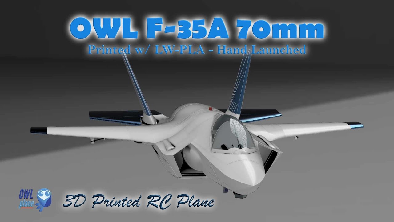
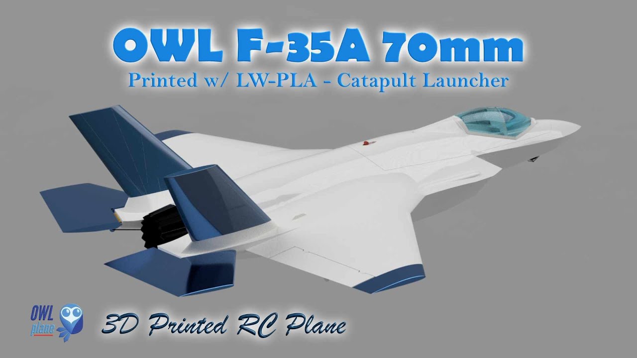
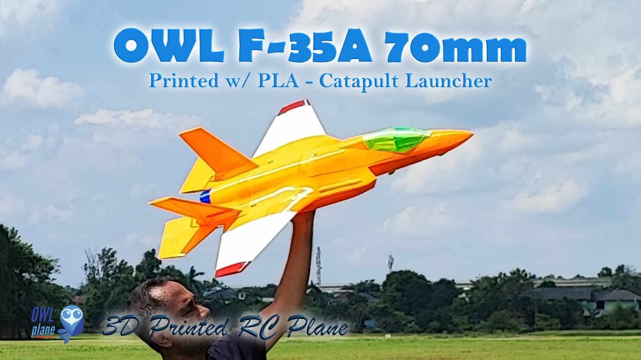
OWL F-35A 70mm EDF
( Semi Scale Model )
~ 3 Variants : (a). "PLA", (b). "LW-PLA Digital Balsa" and (c). "Both LW-PLA Digital Balsa and Foam" Series ~


OWL F-35A - 70mm 6s EDF
We are really happy to release our second model in 2025. This OWL F-35A 70mm model is designed for flexibility and ease of use. Whether you’re a seasoned maker or a weekend hobbyist, we’ve simplified the process to get you from “download” to “takeoff” faster.
Here is everything you need to know:
3 Ways to Print (PLA, LW-PLA “Digital Balsa” and LW-PLA “Digital Balsa and Foam”)
We provide three distinct variants based on your preferred filament. Each variant comes with its own set of STL files and slicing profiles.
Mix & Match: You aren’t locked into one style; feel free to mix parts from different variants to suit your needs.
Powered by OrcaSlicer (New for 2025 and Onward)
Printing is now much more reliable because our profiles are built in OrcaSlicer, which supports the vast majority of FDM printers on the market.
Project Files Included: We don’t just give you the STLs; we provide the full Project files.
The “Easy Mode” Process: If your printer is on our supported list, simply select your machine, choose your filament, and match it to the STL reference code. That’s it!
Custom Support: If your printer isn’t listed yet, don’t sweat it. OrcaSlicer makes it incredibly easy to create a custom profile.
Try Before You Buy
We want you to be confident in your print. Head over to our OrcaSlicer website page to download the profile files for free. You can test them out and ensure everything runs smoothly on your machine before you commit to a purchase.


To make your first flight as smooth as possible, here is a quick guide to setting up and launching your EDF jet:
Recommended Setup
Battery: Use a 6S 2200mAh battery.
Build: Print using the LW-PLA “Digital Balsa” approach (no infill). This keeps the model lightweight, which makes landings much easier.
Launching & Maiden Flight
If you aren’t experienced with hand-launching EDF jets, we recommend using our Catapult Launcher. It eliminates the risk of “human error” or a bad toss.
Practice First: Use the catapult for your maiden flight to get a feel for how the model handles.
Trim & Relax: Once you have the ailerons and elevator properly trimmed, the plane will be much easier to manage, and you won’t have to worry about fighting the controls during launch.
Videos and Pictures
Flying Play List
1:25
1:37
1:59
F-35A 70mm All Printed in PLA in The Pictures


F-35A 64mm – Left Hand is 70mm and Right Hand is 64mm


3 Sets STL Files to Print !

3 Variants of F-35A 70mm Models :
Choose Your Build: The OWLplane Series
We provide three distinct printing versions for these models. Every version has been flight-tested to ensure it’s not only fun to fly but also tough enough to handle high-G maneuvers.

Standard PLA: Great if you’re on a budget or a schedule. It’s the heaviest and most challenging to fly, but as you can see in our videos, it’s still a blast.
Digital Balsa: This is the high-performance choice. It has the lowest All-Up Weight (AUW), though it requires a gentler touch as it is structurally the most delicate.
Digital Balsa & Foam (LW-PLA): Often the “sweet spot” for most pilots—offering great strength without the heavy weight of standard PLA.
Launch Recommendations
To keep your model in one piece, we recommend the following:
Use a Catapult: We strongly advise against hand-launching the heavy PLA series.
Avoid Human Error: Regardless of the model you choose, using a catapult is the safest way to ensure a successful takeoff every time.
Technical Insight: “Digital Foam” & Ribs
When we say “Digital Foam,” we’re referring to the use of gyroid infill during the printing process.
Strength Control: You can adjust the infill percentage to your liking—higher percentages mean a stronger (but heavier) plane.
Internal Ribs: We’ve designed these models with internal ribs to provide maximum support while using the most efficient amount of gyroid infill.
Customization: If you want to modify or remove internal structures to save weight, check out our OrcaSlicer profile page for a step-by-step guide.
*) Below is from F16 part for illustration.


In 2025 and onward, when we release a new model, it should be sliced using OrcaSlicer. If you would like to know more and download the provided profiles, please visit the following page : https://stagingowlplane.web.id/orca-slicer-for-bambulab-and-others/ or click the button below.

Like Playing Lego (PLA, Digital Balsa, Digital Balsa & Foam):
As explained above, here are some pictures after cleaning the parts, they can assemble like playing “lego” blocks.
*) Right side pictures are sample parts from F16 model.


Expected Some Stringing but Easy to Clean (LW-PLA for Some Parts) :
Since active foaming filaments such as LW-PLA is not affected by retraction, some stringings are expected. The good news is that they are easy to clean compared to printing with standard PLA/PLA+.
*) below are sample parts from F16 model.
- Suggested using knife to clean initially.
- Once completed using knife, continue using sandpaper for sanding some strings that still attached to skin.
- Sandpaper could also used to make smoother skin.
- For the plug-in blocks, also use sandpaper to eliminate excessive materials.


Sandpaper Cleaning the Excessive Materials Surrounding Plug-In Blocks :
Sanding parts would make assembling much easier and also cleaner. Excessive materials can be found on the top surfaces. For example, the circle in the picture need to sand so that there is no need to push the part harder later to fit into the next part.
*) a sample part from F16 model.

Sand The Surfaces To Get Smooth Ones :
Comparing surfaces before and after sending it. LW-PLA material let you smoothing surfaces where it would not be applicable with standard PLA or PLA+.


Slicing and Printing
After unzipping the download file, the project file in this example is located under :
1. STLs F-35 70mm\STLs v1.0\1. FUSELAGE 70mm\LW-PLA\B2T2_GR1 & PERI1_B2T2\PERI1_B2T2\PROJECT FILES
Open the project file with orca slicer. It will find fuselage stl files as depicted on the right side screenshoot.
The following PICs are for illustration only (borrowing from OWL Mirage 2000D 70mm)

The following PICs are for illustration only (borrowing from OWL Mirage 2000D 70mm)


The default printer is BambuLab A1. Assuming that the printer is Creality K1C, it need to replace the printer from BambuLab A1 to Creality K1C (we use Creality K1C as an example, if yours is BambuLab A1, than it is very simple, you just need to submit to print the object).
Also, since the project file is for LW-PLA, it needs to select LW-PLA filament for the filament setting.
Where the profile code is PERI1_B2T2, it means that needs to find the PERI1_B2T2 process profile code. Once completed, verify that all machine, filament and process are correctly selected (instead of for BambuLab A1, now is for Creality K1C with same LW-PLA filament and process ref. code PER1_B2T2).
If your 3D printer is not Creality K1C, you need to find yours or create one if can not find it from the list. Just copy the relevant settings from already provided settings.
Specification and Some Details
- Wing Loading : 83.3-106.5gr/dm^2.
- AUW/Flying Weight : 1800gr-2300gr (with 2200mAh 6s - 3300mAh 6s).
- Wing Area : 21.6dm^2.
- Wing Cube Loading (WCL) : 17.9-22.9.
- Flight Performance Category : Racer.
- Radio Channels : Throttle, Aileron and Elevator.
- Length : 1040 mm.
- Wing Span : 743 mm.

Spar Requirements :
- 1 x 8mm OD and with 570mm long fiber carbon tube as fuselage-wing spar.
Locking Belt for Attaching Wings to Fuselage :
- 4 x “LOCKING-BELT # GR3”


Aileron/Wing Control Surfaces Rods:
- Use about 1.5-2.0mm rod to assembly ailerons.
- Use about 2.0-2.5mm rod as guide or support for assembling ailerons.
- Use about 2.0-2.5mm rod as guide for assembling hstab.


Please Use 15mm Pins to Assembly FUSELAGE-3 and 4.
To glue FUSELAGE-3 and FUSELAGE-4, need to use 4 x 15mm pins as shown below. The pin STL files can be found under : “1. STLs F-35 70mm\SUPPORT v1.0\PINS – please use 15mm PIN”.


Cut Some Areas for LW-PLA Parts Only :
Only for FUSELAGE areas printed with LW-PLA (the parts designed that way to avoid travelling).


ESC Management Positions :
Feel free to locate the electronics for getting the correct CoG.


Electronic Position Implementation.


70mm EDF Bracket and Installation :
If you would like to test the EDF brackets before purchasing the files, you can download the EDF bracket STL files from the following :
Right side pictures show how 70mm EDF installed into the fuselage.

*) For illustration only; the picture taken from 64mm EDF when intake lip removed only.


*) The pictures are from OWL ViperJet 70mm.
Two sets of EDF brackets can be used. The one with intake lip removed, the one with fixed/taped intake lip (generic bracket).
You can find the bracket STL files under “1. STLs F-35 70mm\SUPPORT v1.0\F-35 EDF BRACKETS 70mm EDF”.
For the first picture, you do not need to glue the fixed intake lip EDF into its bracket but you need to screw left and right side arms before attaching to the fuselage so that the bracket will not easily separated from its bracket. If your EDF motor is not in the list above, you may want to use the the fixed intake lip bracket (the bracket STL files are free to download, see above download button).
For the second picture, it uses hot glue for 70mm EDF with no intake lip (removed intake lip).


EDF Lid Assembly :
Use pins to assembly/glue.

Following the Instruction below To Assembly The Horizontal Stabilizer :
Two versions are provided to assembly the horizontal stabilizers :
– using glue.
– using screw.
It is recommended to use screws. When the event elevator broken due to hard landing for example, we still can easily replace the broken horizontal stabilizer with the new one.
For the hinges, we provide three different hole sizes so that it would be best fit (not too tight and not too loose). They are named as S, M and L for Small, Medium and Large.
Please find below the instruction to assembly the screw version (recommended).


Please find below the instruction to assembly the screw version (recommended).


3 hole options are available for glue or screw versions.

Canopy Assembly with Pins and Rods :


Center of Gravity (CoG) :
- See the following marks for CoG location

How to Launch OWL F-35A 70mm EDF Model :
Two methods are suggested to launch the model. The first one is to use OWLplane Catapult Launcher. Please visit OWLplane Catapult Launcher product page menu under “SHOP & PRODUCT LIST” tab after hovering the mouse over (you can use your own Catapult Launcher so that you just need to print the hook adapter). The second one is by hand launching.
It is recommended to launch the model by utilizing OWLplane Catapult Launcher or your own launcher since it is human error free.
#1 – By Utilizing OWLplane Catapult Launcher.
Watch the following videos how easy it is to launch the rc model with OWLplane Catapult Launcher and human free errors.

#2 – By Throwing (Not Recommended).
Please print the model using LW-PLA with no-infill or we call it “Digital Balsa” type of print. Make sure you use a powerful EDF motor that can have static thrust stronger than the model AUW itself (having more than 1 thrust and AUW ratio).
Follow the following tips to launch :
– Lean your body backward.
– Put your fingers on designated locations (shown in the following section below).
– Start throwing by also moving your body forward.


*) Above pictures are illustration only, using 50mm BAE Hawk T1.


Note : Above pictures are from launching OWL F-35A 70mm 6s EDF with 6s 2200mAh and printed with LW-PLA no infill.
Print The Launcher Adapter Below :
To get some degree of wing incidence (if the catapult launcher can not give some degree of wing incidence after laying the model on), please print the launcher adapter as shown below.
If you would like to use your own, you may need to skip the adapter but just need to print the hook.


If you plan to launch the model with our own catapult launcher, please print the part shown on the right side. All parts are located under “1. STLs F-35 70mm\SUPPORT v1.0\CATAPULT LAUNCHER”.
- 2 x 8mm or 10mm OD with 500mm length tubes (for the arms).
- 1 x 5 or 6mm OD with 10mm length (for the hook).
More details regarding assembling OWLplane catapult set can be found from OWLplane Catapult Launcher product page.


Use tape to create tabs as shown in the picture. The left and right arms should be located approximately where CoG rest on them also as shown by the right side picture (use rope tool to help).


Finger Resting for Hand Launching :
If you choose to launch by throwing, please put your fingers as shown in the following pictures.
Optional : Fiber Tape Protecting The Model During Belly Landing.
By using fiber tape attached to the belly skin, it will protect a model during landing from rough surfaces. Not only protecting, you may no need to clean the belly after sometime by replacing it to get back clean.
We have tested it and really happy with the result. The model is still in a good condition after landing it on rough surfaces.
*) Using F16 belly part as illustration only.


Weight and Time Estimation :
Following tables show the weight of printed parts, number of required filament rolls and time required to print. But the number may vary from printer to printer due to:
– Stepper Jerk value.
– Stepper Acceleration value.
– Steps per unit (either calibrated or uncalibrated).
– Extruder quality/condition.
– Nozzle quality/condition.
– Filament quality/condition.
– Etc.

Here are the summary table :

Klipper Firmware Does Not Accept “#” / Hash Character
Unfortunately the Klipper firmware does not accept the “#” / hash character when naming the file. More and more 3D printers nowadays and upcoming most likely will use the Klipper firmware where when using previous firmware such as Marlin, Prusa, etc. do not prevent it from processing.
Since our naming convention for our g-code files utilize the “#” character and already since we started the OWLplane, we still keep them until our new release models dated after July 2024 (after BD OWLjet 70mm 6s EDF).
No worry, to use our g-code files, just need to remove the “#” character, that is it !
Fore example :
“FUSELAGE-1 # P3_H15″ replace the file name with “FUSELAGE-1 P3_H15”
Note : no “#” character is used in the new file name.
How To Extract Our Zip Files
Somehow when the folder path is too long, files and directories can not be extracted directly to a destination directory. There is a workaround for this, just follow the guide below. What you need to follow is to double click zip file until you find the directory. From there, right click to invoke a “copy” command. After that, just copy and paste the directory into your destination directory. That is it !


Table of Contents
Update History
None.
Recommended Setup


- Motor Options : Powered with 70mm EDF 6s (see above but not limited to).
- Servo Options : 4 x 12gr servos for aileron and elevator (left and right).
- ESC Options : ESC 80A, please consult to your EDF manual if safe enough to use that rated Ampere value.
- Battery Size : LiPo 6s 2200mAh - 3300mAh rated 70C with weight around 400-600gr.
Tools and Materials
- Printer, in general 210mm x 210mm x 210mm (W x L x H) for all OWLplane Models.
- Filament: LW-PLA from ColorFabb, ePLA-LW from eSUN and PolyLight 1.0 from 3DLabPrint.
- CA glue with accelerator. Use thick glue to join surface to surface. Use thin CA glue for coating the joint surface areas.
- Velcro sticker/polyester hook and loop peel-n-stick self-adhesive for locking the battery.
- Fine sandpaper.
- Sharp knife.
- Screwdriver and/or allen wrench for chosen screws/bolts.
- Pliers, needle-nose pliers, nippers.
- Steel bolt cutter.
- Dremel/rotary tool for cutting carbon fiber tubes and rod with more than 2.5mm.
- Electric drill, its drill-bit size from 1.5mm - 5mm and step cone drill.
- Propeller shaft reamer or hole puncher reamer.
Hardware Needed
For Fuselage and Canopy:
- Self tapping screw M2.5x20mm or M2x20mm with their washers (optional) for mounting left and right wings including fuselage lid - 8x (4x wings and 4x EDF lid).
- Ballpoint pen springs for Canopy - 1x.
For Aileron and Elevator:
- 1.5 - 2.0mm rod for aileron and elevator hinges (ER308L - TIG Stainless Steel Rod but preferred TIG Aluminum Rod instead).
- 2.0 - 2.5mm rod for aileron and elevator pushrod (ER308L - TIG Stainless Steel Rod).
- 2.0 - 2.5mm rod for aileron, elevator and canopy support (ER308L - TIG Stainless Steel Rod).
- Landing gear wheel stop set collar D2.1mm or D2.6mm for aileron and elevator 4x.
- Linkage stopper D2.1mm or D2.6mm for aileron and elevator - 4x.
- Self tapping screw M2.5/M2.0x15mm or M2x15mm for mounting left and right aileron servos - 8x.
- Self tapping screw M2.5/M2.0x15mm or M2x15mm for mounting left and right elevator servos - 4x.
*) Illustration only
Setup for Servo Travel/Throw
Suggested setup for medium travel/thrown are depicted below and you may adjust the setup according to your need.
Please pay attention to start and end measurement location.
- Aileron = 9mm.
- Elevator = 18mm+ (Yes, Elevator needs more throw than usual other models).
Neutral Throw for Elevator

Assembly Figures
F-35A 70mm Fuselage Assembly


F-35A 70mm Wings Assembly


F-35A 70mm Stabilizer Assembly


F-35A 70mm Canopy Assembly

